In this post I hope to quickly cover how I use pfSense to provide easily reachable management networks for simulations within VIRL.
Below is a list of the technology I use in this lab environment:
- pfSense SG-1000 running 2.4 BETA
- Cisco VIRL_ — Core 0.10.29.12_
- VMWare ESXi 5.5 Update 1
- Generic VLAN Aware Layer 2 Switching
I will not go through the entire installation of Cisco VIRL. I am just going to go through what I do in my personal environment to allow the FLAT & FLAT2 networks to be routable to the world. I have the SNAT network setup in a similar fashion, but I do not often use it so I will only mention SNAT this once.
I will also not go through the process of adding VLANs and interfaces to the pfSense SG-1000. If this is something you would like me to cover in more detail just leave a comment or shoot me a tweet and I would be glad to help you out!
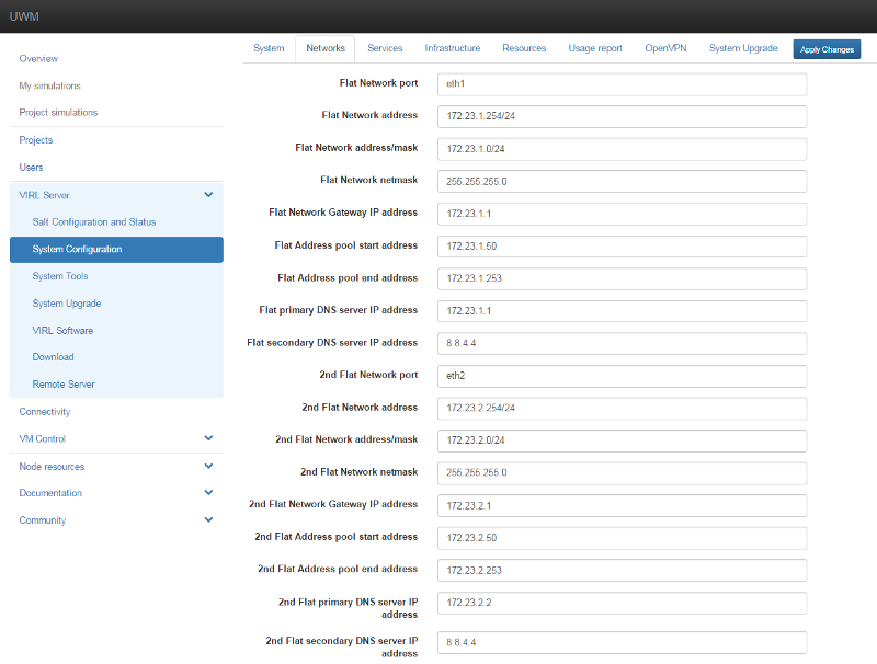
Instead of using the stock 172.16.1.0/24 & 172.16.2.0/24 FLAT networks, I have updated the VIRL configuration for my local environment. This evolved changing the second octet from 16 to 23. Once that is completed I saved the changes in the VIRL admin portal and allowed it to go through the LENGTHY process of reconfiguration. This takes a while…grab a drink…
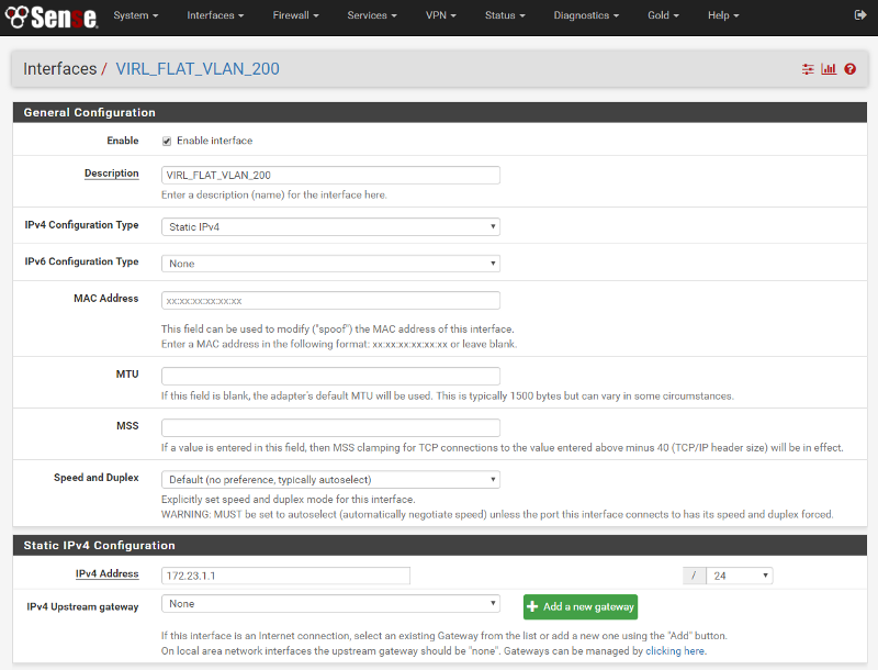
After that I setup a VLAN (I used 200) and assigned it to an new interface on my pfSense SG-1000. I then give that interface the gateway IP of the FLAT network (172.23.1.0/24) and enable:
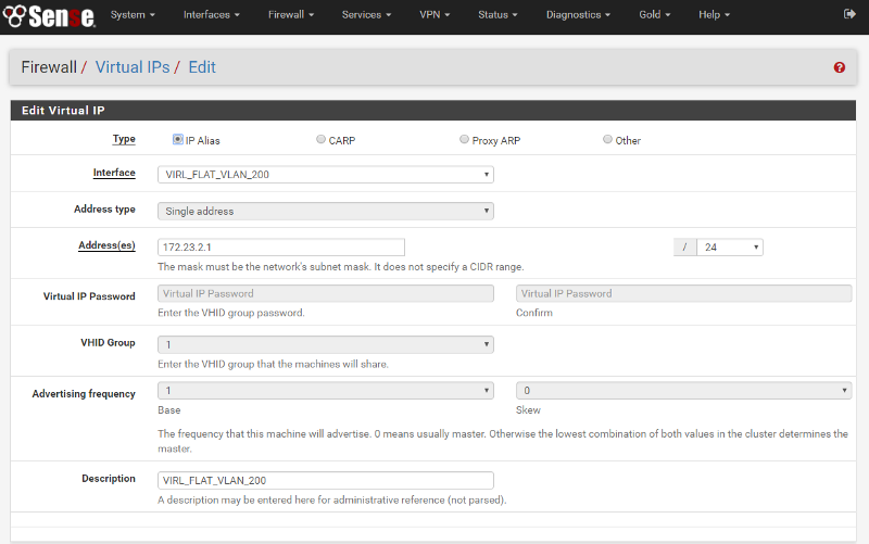
After everything is saved I added the FLAT2 gateway as a secondary virtual IP on the same interface:
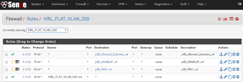
After this configuration is done all that is left is to add a rule to allow traffic to pass through the interface. The last rule in this list in the one that allows all traffic originating on the Interface to access the Internet. The top three rules are added by pfBlockerNG, a package I highly recommend if you are a pfSense user!
Note…you DO NOT need to enable DHCP on your pfSense box! DHCP is handled by the VIRL system.
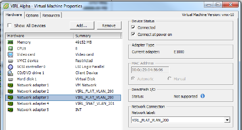
Ok, now all the pfSense prep is complete! Take the time to trunk your new VLAN through your infrastructure and into your VMWare environment. Once the VLAN is in ESXi it is as easy as applying the VLAN to the FLAT and FLAT2 interfaces on your VIRL VM. In most cases this is Network adapters 2 & 3:
Once this is complete you should be able to ping the gateway IPs from the FLAT (br1) and FLAT2 (br2) interfaces:
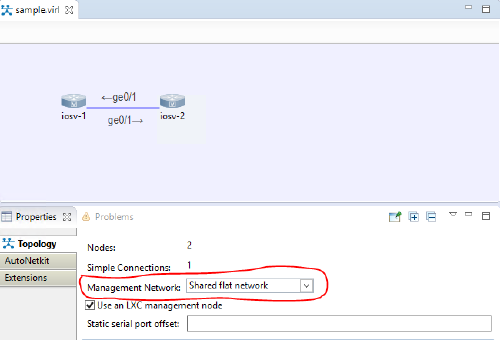
Great! Now…how do you use this in a simulation? I created a quick two nod simulation to show the usage. The main thing to pay attention to is the use of the “Shared flat network” setting in the Management Network dropdown while you are designing your sim. You get to this Properties screen by clicking the background in the simulation window:
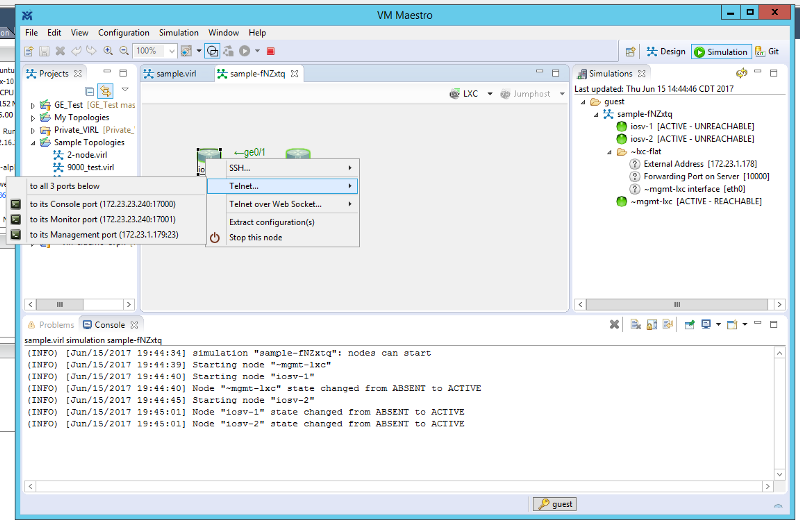
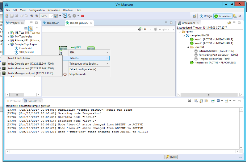
Now save your sim and launch it. Once you launch the sim you will see that the nodes show “ACTIVE — UNREACHABLE”. Also, if you right click on the device and hover over “Telnet…” you will see that a 172.23.1.X IP has been assigned to the management port on the device:
While the IP is assigned to the device, it is not automatically configured on the device. If you log into the console of the device you will see that there are two interfaces, even though only one is shown on the sim. The first interface, Gi0/0 in this case, is connected to the imaginary back-end management network. You will need to configure this interface to use DHCP. It will pull the IP it has been assigned and you should be able to ping out to the gateway and beyond. I recommend using a mangement VRF just like you would in production. This way management will not interfere with your lab. See my config below:
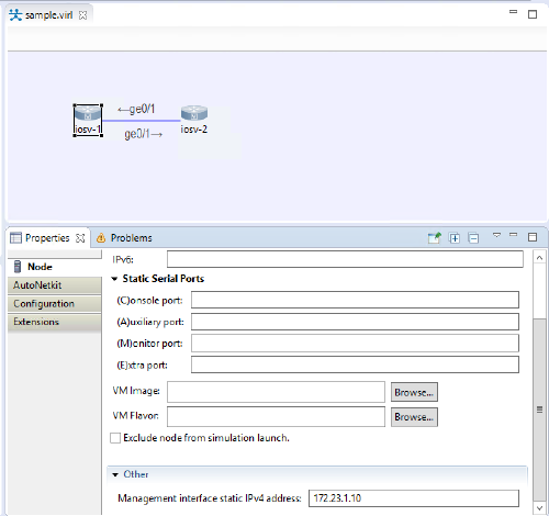
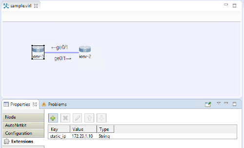
As you see from the output above, DHCP hands out the IP VIRL has assigned. It must be noted this IP will change every time you launch the sim! So, how do you set a static IP? See the screen cap below. In the latest Alpha: While in the design pane you would click on the device, then scroll down to the bottom where it asks you to enter the Management address. If you enter an address that is not in the management scope, it will error when you try to launch the sim. In earlier versions of VIRL you will need to enter the static_ip extension manually. I have captured that in a screen shot as well.
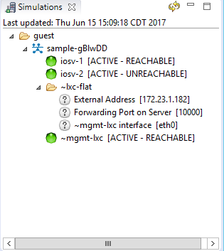
Now when you launch the sim you will see that the telnet IP for node 1 is the static IP we assigned:
You will also notice that the device become reachable after you configure the management IP properly:
Now you just need to configure your remote access method of choice (Telnet/SSH) and you are off to the races!
I hope this helps and if you have any questions, corrections, or additions please leave a comment or hit me up on twitter!
No comments yet — be the first.
Say something
Thank you
Your post has been submitted and will be published once it has been approved.
OK